
SA-1 A/G Master Mode
Objectives
1. Identify the A/G control elements of the UFCP to include the declutter key and the HUD function key.
2. Identify the MFD WPN display and the A/G control elements of the display.
3. Identify the control features of the DTS, Armament Master Switch, CMD Master Switch, HOTAS, and VTR
4. Identify the symbology on the T–38C F–16 emulation HUD display in the A/G master mode to include the CCIP,
MAN and CCRP sub–modes.
5. Interpret the weapons parameters and data displayed on the T–38C F–16 emulation HUD.
6. Interpret the data presented on the No Drop Bomb Scoring system and the Summarized Scoring Display.
Assignment
1. Read Lesson SA–1, A/G Master Mode in the SG and complete the review exercises.
2. Read the applicable air–to–ground weapons information in each of the T–38C Flight Manual avionics component
sections listed below to become familiar with the A/G weapons controls and displays in section I:
a. Avionics Master Modes
b. Up Front Control Panel (UFCP)
c. Multifunction Display (MFD)
d. Head–Up Display (HUD) F–16 Emulation
e. Video Tape Recorder (VTR)
f. Data Transfer System (DTS)
g. Air–to–Ground (A/G) Master Mode
3. Review the applicable A/G sections of the T–38C Weapon Delivery Manual, T.O. 1T-38C-34-1-1.
Introduction
1. The T–38C does not have hard points to mount bombs on or an actual gun to shoot. The aircraft’s new avionics
provide the simulated weapons capability for the A/G environment. The system simulates carrying various types and
quantities of free fall bombs and 2 separate types of simulated A/G guns carrying 450 rounds of ammunition.
2. The A/G master mode contains three sub–modes: Continuously Computed Impact Point (CCIP), Continuously
Computed Release Point (CCRP) and Manual (MAN).
a. In the CCIP sub–mode all of the flight conditions, range to target, and weapons delivery parameters are
combined into a computing pipper/reticle. The aircraft is flown to get the pipper over the target and the bomb(s)
released.
b. In MAN mode a reticle is placed on the HUD in a roll stabilized position equal to the mil depression required
for the selected weapon and chosen release parameters. The pilot is the computer. MAN mode was the method of
delivery for most fighter/bombers during WWII, Korea and Viet Nam.
c. In the CCRP sub–mode all of the flight conditions, range to a designated target, range to the pull–up point,
optimum weapon release and weapons ballistics parameters are combined to provide an azimuth steering line
(ASL) with a pull–up cue and a solution (weapon release) cue on the HUD. The CCRP symbology is optimized for
a basic loft delivery with a pull–up just prior to weapon release. It can also be used for delivery from medium
altitude in level flight. (Primarily used for precision guided munitions.)
2
3. The CCIP reticle is also used with the gun in a strafing pass. For the T–38C 20 millimeter gunsight, a horizontal
“in–range” cue attaches to the top of the pipper when the slant range is 4,000 ft or less to the target. For the A–10 30
millimeter gunsight, the “in–solution” cue is a range readout in NM (x.x) which appears below the A–10 gun cross
when the slant range is 4.9 NM or less to the target. Pulling the trigger fires the simulated gun across the selected
target.
4. A No Drop Bomb Scoring (NDBS) system is incorporated in the overall system to give feedback on how well the
bombing pass was executed. The NDBS compares the nominal predetermined parameters with the actual flight
parameters and determines the point of impact of the bomb. This system, together with the VTR, provides a visual
record of the bombing run. The NDBS data is also stored in the MDP and downloaded via the DTS.
5. The avionics system includes a simulated Counter Measures Dispensing (CMD) system. The system simulates
dispensing flares and chaff bundles in two unique patterns. The programs provide for a “combat” or “escape”
dispensing sequence.
6. This lesson combines all of the new avionics that were introduced in previous system lessons. It is assumed that
detailed “how–to” instructions are not needed to set up or enter the A/G master mode.
Information
A/G Controls and Displays
Objective 1 — Identify the A/G control elements of the UFCP to include the declutter key and the HUD function key.
Objective 2 — Identify the MFD WPN display and the A/G control elements of the display.
Objective 3 — Identify the control features of the DTS, Armament Master Switch, CMD Master Switch, HOTAS, and
VTR.
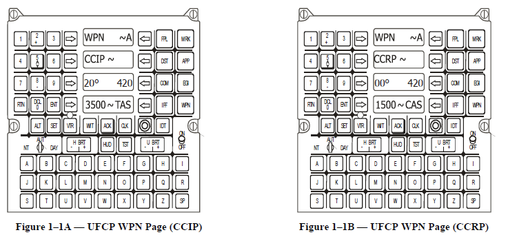
Up Front Control Panel (UFCP)
1. The UFCP provides the means for selecting the type of HUD, the digital airspeed display, the weapons program,
and the three A/G sub–modes. Figures 1–1A/1B show UFCPs with two of the weapons function page selections (CCIP
and CCRP) displayed. Use UL-2 to choose the CCIP, CCRP or MAN sub–modes. Use UR-1 to toggle between the
seven weapons programs: A, B, C, D, E, F and Gun. These seven programs are all predefined with the MPC/JMPS and
loaded into the MDP via the DTS. UR-4 is used to select the velocity scale type, TAS or CAS, displayed in the HUD
with the A/G mode. The other information displayed on the weapons page is loaded via the DTS or entered via the
MFD weapon page.
Multifunction Display/Data Transfer System (MFD/DTS)
1. Pressing the DCL key while in the A/G Master mode will remove the items that you preselected with the
MPC/JMPS and loaded with the DTS. The MFD may be used to select the A/G master mode and to make weapons
parameter choices. MOSB MR-5 on the PFR/HSD display is used to select the A/G master mode. MR-3 on main menu
page is used to gain access to the weapons page. Figure 1-2 shows the display after MR-3 is pressed.
2. For the A/G master mode the following MFD weapons parameter choices are available. Pressing each MSOB will
allow editing of the associated parameters or resetting the quantities.
a. RELEASE ALT (ML-3) – 0000 to 9,999 ft MSL. A leading zero is required for altitudes less than 1,000 ft.
b. RELEASE VELOCITY (ML-4) – 000 to 999 KCAS.
c. DIVE ANGLE (ML-5) – 00 to 90 degrees. If the planned dive angle is less than 10° a leading zero is required.
d. CONFIGURATION (ML-6) – CLEAN or POD.
e. CHAFF (MB-2) – 60 bundles.
f. FLR (MB-4) – 30 flares.
g. SHELLS (MB-5) – 450 rounds.
h. MSLS (MB-6) – 4 missiles.
i. RIPPLE (MR-6) – 000 to 999 ft. This value has no function except for training purposes.
j. BREAK-X (MR-5) – 00100 to 99900 ft AGL.
k. (MR-4) (if MR-3 is A, B, C, D, E, F) WPN – BDU–33/CBU-87/MK-82H or L and MK–81/83/84/117, or
(MR-4) (if MR-3 is GUN) GUNSIGHT – A-10 or T-38
l. PROG (MR-3) – A, B, C, D, E, F or GUN
m. RPTR (MR-2) – Repeater mode for selected MFD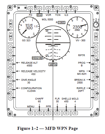
Figure 1–2 — MFD WPN Page
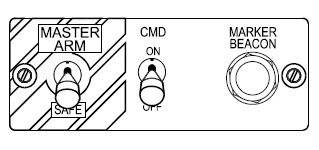
Figure 1–3 — Master Arm & Counter Measures
3. The Combat Weapons Delivery Software (CWDS), program provides the weapon specific information to determine
the preflight values used for each weapon.
4. Weapons data will normally be modified with the MPC/JMPS and loaded into the aircraft via the DTS. Each
weapons program (A, B, C, D, E, F, GUN) contains the following information:
a. Weapon type.
b. Release type (single or ripple).
c. Break–X altitude (minimum altitude for recovery).
d. Nominal release parameters (altitude, speed, and dive
angle).
e. Pipper depression (manual release).
Master Switches
1. Master Arm Switch — The master arm switch is located on
the instrument panel to the left of the MFD, see Figure 1–3. The
switch has two positions: ARM and SAFE. When the switch is
placed into the ARM position all simulated weapons inventories
are reset to their initial quantities.
a. SAFE (down) — All weapon releases are disabled.
CMD is available.
b. ARM (up) — The simulation of weapon release is
enabled with this switch position. A/G master mode must
also be selected to complete the weapon release simulations.
2. CMD Master Switch — This master switch is located to the right of the Master Arm Switch on the same panel, see
Figure 1-3. This switch also has two positions: ON and OFF. When the switch is placed to ON all simulated counter
measures inventories are reset to their initial quantities.
a. OFF (down) — Flare and chaff dispensing is disabled.
b. ON (up) — Flare and chaff dispensing is enabled.
(1) Press the CMD switch, on the right throttle, up to select the “combat” program. This delivery mode
provides 15 flares at 2–second intervals and 30 chaff bundles in 4–second intervals. Two complete programs
can be run with a full load of chaff and flares.
(2) Press the CMD switch, on the right throttle, down to select the “escape” program. This delivery mode
provides 2 flares in 2–second intervals and 4 chaff bundles in 4–second intervals. Fifteen complete programs
can be run with a full load of chaff and flares.
(3) A tone is heard in the helmet when the program is executing.
(4) If CHAF is selected via the UFCP then the release tone is transmitted over the VHF radio frequency.
c. When a dispensing program has started it cannot be modified or overridden by another program. If less chaff
and flares are available than is normally expended during that program it will use all that are available.
Hands On Throttle and Stick (HOTAS)
1. The Hands On Throttle and Stick system allows the pilot to select master modes and control simulated weapons
delivery without moving the hands from the flight controls, see Figure 1–4. This concept reduces pilot workload by
allowing the control of these functions without looking down inside the cockpit. The HOTAS switches used in the A/G
master mode are:
a. Master Mode Switch (MMS) — used to select the air–to–ground master mode. Pressing the switch AFT
toggles to the A/G master mode. Pushing FWD toggles to A/A master mode; pushing down toggles to NAV master
mode. Re-commanding the current Master Mode, decrements the PFR EHSI ranges from 20, 10, 5, 2.5 NM and
repeats. If in HSD, range scale is decremented from 120, 60, 30, 15 NM and repeats.
b. Default Display Switch (DDS)
(1) The FCP DDS toggles between the PFR and HSD MFD display. If any other display is on the MFD when
the DDS is pressed, the PFR display will be presented. The switch also terminates Blanking but not the MFD
Repeater option. Cockpits remain independent except in the repeater mode.
(2) When the RCP DDS is held for a greater than 1.0 second duration, the switch toggles HUD-on-MFD
(RCP only) ON and OFF. Also, a short duration (less than 1.0 sec) click of the RCP DDS switch will
unblank the HUD and the MFDs in both cockpits.
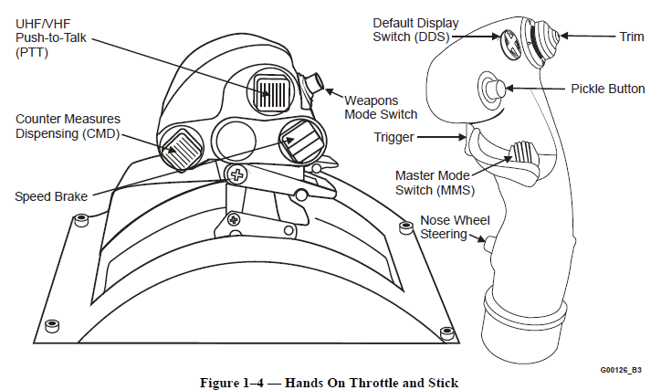
c. Weapon release switch (Pickle button) — releases the bomb or initiates the release sequence in a delayed
release (CCIP delayed or CCRP).
d. Trigger — used to fire the simulated gun.
e. A/G target designation switch — In the air (weight-off-wheels) and in A/G master mode, the nosewheel
steering switch is used to identify and enter ground targets as steer points into the MDP. In the air (weight-offwheels)
and in A/A master mode, this switch toggles ON/OFF an AIM-9 uncaged function (simulated ) by
enlarging the seeker circle display on the HUD. In the air (weight-off-wheels) and in NAV master mode, this
switch cycles the PNS selections (EGI, TCN, VOR, ILS (or LOC, BC), SCA and then repeats
f. Weapon mode switch — If CCIP or CCRP is selected on the UFCP WPN page (and A/G Master Mode is
selected on MFD MR-5 or via MMS on stick), the throttle switch toggles between CCIP bombs, CCIP guns, and
CCRP. If MAN is selected on the UFCP WPN page, the switch toggles between WPN (bomb) MAN and MAN
GUN. In NAV mode and with TCAS ON, this switch commands TA, if currently in SBY, A, C or RA. If in NAV
mode, TCAS ON in TA mode, this switch commands RA.
g. Counter Measures Dispensing (CMD) switch — allows the pilot to select which of the two simulated chaff
and flare dispensing programs to activate.
2. The other switches and buttons, while not directly related to the A/G master mode, allow the pilot to control the
aircraft. Switches that may be important in a loss of situational awareness are the Default Display Switch (DDS), which
allows immediate selection of the PFR display on the MFD, and the MMS down position to select the NAV master
mode. These two switches will provide immediate instrument references, in a “head–up” and “head–down”
environment, to allow the pilot to recover the aircraft, if required.
Video Tape Recorder (VTR)
1. The video tape recorder provides a visual record of the bombing or strafing run. The VTR will normally be ON
throughout the mission but it is recommended that the VTR be turned ON when you select the A/G master mode as a
minimum.
2. A black rectangular event mark (CTVS mark) is placed on the VTR tape to indicate when the pickle button is
pressed or the trigger is pulled. This event mark will be continuous as long as the pickle button is pressed or the trigger
is pulled. The same event mark is placed on the tape when the NDBS Score or Summary page is displayed. This
information will be used when the VTR tape is analyzed in the mission debrief.
A/G Master Mode
Objective 4 — Identify the symbology on the T–38C F–16 Emulation HUD display in the A/G master mode to include
the CCIP, MAN and CCRP sub–modes.
Objective 5 — Interpret the weapons parameters and data displayed on the T–38C F–16 Emulation HUD.
1. This segment deals with the A/G master mode displays on the F–16 emulation HUD. For simplicity the discussion
of the A/G master mode is broken into four sub–segments: CCIP bombs, CCIP guns, Manual and CCRP.
2. If CCIP or CCRP mode is selected on the weapons page of the UFCP, CCIP is the default mode when the MMS is
toggled AFT. The weapons mode switch on the throttle is pressed to cycle from CCIP bombs to CCIP guns to CCRP.
3. The type of delivery (CCIP/CCRP/MAN) selected is displayed on the lower left side of the HUD. The selected
delivery mode (A, B, C, D, E, F or GUN) is also displayed. Each delivery mode has a weapon (BDU–33, CBU-87,
MK-82H or L, or MK-81/83/84/117 or for GUN A-10 or T-38 or for GUN A–10 or T–38) associated for that delivery
and is also displayed on the HUD (see Figure 1–5).
4. The manual mode must be selected on the UFCP weapons page before it can be used. The manual sight can be
used for either bombs or guns. A milliradian (mil) depression, from the Combat Weapons Delivery Software, is
required to bomb or strafe using the manual sight. Each weapon will have a specific sight depression that is required to
be used for each set of release parameters. The weapons mode switch on the throttle is pressed to cycle from WPN
(bomb) MAN to MAN GUN.
5. The Continuously Computing Release Point (CCRP) mode provides an “indirect” weapons delivery capability,
which include loft or toss type deliveries. This type of delivery maneuver is normally used for guided munitions or area
weapons.
6. Individual bombing or strafing targets are normally predefined (lat/long and elevation). Any DEST point (with the
exception of DEST 200, 500 thru 509, and ICAO) may be used as a target.
CCIP Bombs
1. When entering the A/G master mode, changes are made to the F–16 emulation HUD display to show specific
weapons information not included in the NAV master mode or the A/A master mode. The following information is
added, replaced, or changed on the HUD in the CCIP sub–mode (see Figure 1–5):
a. The avionics master mode/sub–mode indicates CCIP and the weapon program (and the associated weapon)
that is selected.
b. The weapon delivery status is changed to ARM from SAFE when the master arm switch is moved to the
armed position.
c. Under the Max G and avionics master mode/sub–mode data block is a read out of the gun rounds remaining
and chaff/flares remaining.
d. The bank angle scale and bank indicator are removed.
e. The slant range to the target is computed via algorithms and displayed below the altitude alert data block. The
range is displayed with three digits representing hundreds of feet. A time to steer point is displayed below the slant
range. For a delayed release, the delay time replaces the time to steer point readout and counts down to release, see
Figure 1–6.
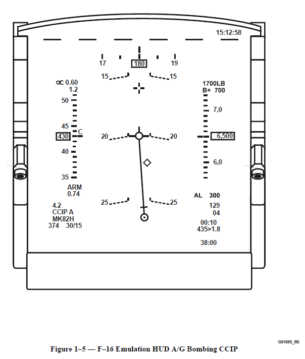
f. A pipper (circle with center dot) and a bomb fall line (BFL) are added to the HUD. The BFL connects the
pipper and the flight path marker. If the required pipper depression is greater than 170 mils a delay cue
(perpendicular line) is added to the BFL above the pipper.
g. A LOW cue is displayed in the CCIP and Manual sub–modes for the CBU–87 if weapon release will result in
fuse activation below the designed Height Of Function.
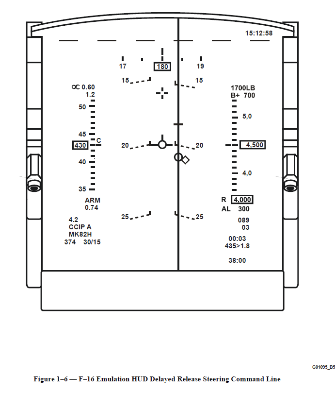
h. During a delayed release, after the pickle button is pressed, the BFL is removed and a command steering line
(vertical line) is added. A solution cue (perpendicular line) is added above the FPM to indicate the actual release
point.
i. In the CCIP guns A–10 mode, a short horizontal line attached to the top of the A–10 “cross” and a digital
range (nm and tenths) readout under the “cross” appear when the slant range to the target is 4.9 NM or less.
j. In the CCIP guns T–38 mode; an “in–range” cue, horizontal line, appears attached to the pipper when the slant
range to the target is 4,000 ft or less.
k. A bullseye bearing and range readout is located just outside of the IFOV in the bottom left corner of the HUD.
When selected on the UFCP, it shows the bearing and range from the selected bullseye point to your aircraft.
G01093_B5
15:12:58
17 180 19
7,0
6,500
6,0
50
45
430
40
35
C
00:10
435>1.8
38:00
4.2
CCIP A
MK82H
0.60
1.2
374 30/15
15 15
25 25
ARM
0.74
129
20 20
04
Figure 1–5 — F–16 Emulation HUD A/G Bombing CCIP
8
l. When the UFCP declutter key is pressed, the A/G display data selected prior to flight on the MPC/JMPS is
removed from the HUD.
2. The CCIP sub–mode provides a continuous computation of the ground impact point based on flight parameters,
range to target, and the pre–defined weapons trajectory parameters. With the pipper displayed on the HUD the aircraft
is maneuvered to put the pipper on the target, using the pre–defined pattern and parameters, and release the bomb. The
entire bomb release sequence can be broken down into three phases: CCIP before pickle, CCIP at and after pickle, and
pull–up.
CCIP Before Pickle — This phase includes all of the preflight computations and maneuvering the aircraft into proper
position to release the bomb.
1. If the predetermined pipper depression is less than 170 mils then bomb release will be immediate upon pressing the
pickle button.
2. If the depression is greater than 170 mils then the pipper is placed at the 170 mil depression and a delay cue is
presented 15 mils up from the pipper on the BFL, see Figure 1–5.
3. The BFL length represents the mil depression for the weapon until it is 170 mils. Beyond this point the target will
be outside the IFOV of the HUD or below the nose of the aircraft when in position to release the bomb.
4. This portion of the bombing pattern is flown the same whether the release is immediate or delayed. In both
situations, fly the pipper to the target. The only difference is when the bomb is actually released.
CCIP At and After Pickle — This phase includes that portion of the bomb run from pressing the pickle button to
release.
1. When the pickle button is pressed the point on the ground that is indicated by the pipper is designated. At the same
time the BFL disappears and the pipper is locked on the aim point as long as it is in the TFOV of the HUD and the
pickle button remains depressed. An event mark is placed on the VTR tape.
2. If the release is not delayed, the bomb is released when the pickle button is pressed.
3. If the release is delayed, the BFL disappears and a command steering line is displayed. Also, the delay cue is
replaced by the solution cue. The aircraft must be flown to align the center of the FPM with the command steering line.
If you were tracking inbound to the target before you pickled, then the command steering line should just be an
extension of your current track.
a. While flying the command steering line, continue to depress the pickle button until the solution cue is reached,
see Figure 1–6.
(1) If the release time is delayed 4 seconds or more then the solution cue is placed 70 mils above the FPM.
(2) The computed time to release (in seconds) is displayed on the HUD under the slant range. The time will
count down approaching the release point.
(3) As the time to release decreases the solution cue will move down toward the FPM.
b. When the center of the FPM reaches the solution cue the bomb is automatically released by the MDP.
4. The current dive or bombing pattern can be continued if above your pull–up altitude or the pull–up can be initiated
while flying the command steering line. The computer will compensate for the change in dive angle and adjust the
solution cue or actual point the bomb is released. If you pull–up, the time to release will be shortened because of the
loft given to the bomb.
5. The FPM will flash after the bomb is released as long as the pickle button is pressed.
Pull–Up — This phase of the bomb run normally starts after the bomb is released. If the release is delayed the pull-up
can begin after the pickle button is pressed.
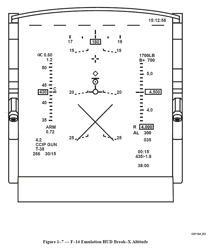
Break–X
1. A large break–X flashes on the HUD to alert the pilot of dangerous proximity to the ground during weapons
delivery (A/G master mode selected), based on a preset altitude. For IFF that altitude is the last DTC set values
(nominally, 100 feet for strafe, 400 feet for bombs). When the break–X is displayed, (see Figure 1–7) the pilot must
start a 4–G pull–up within 2 seconds to recover the aircraft from the dive. When the predicted recovery altitude is
above break–X altitude the break–X display goes away.
2. The recovery height is calculated based on radar altitude. If radar altitude is not available, the height is based on
barometric altitude minus the currently selected steer point altitude. If both radar and barometric altitude are not
available, the CCIP/Guns sight will not be displayed. In this case a flashing NO BREAK X warning is displayed on the
HUD. This warning cannot be deleted by using the UFCP ACK key.
3. The break–X altitude is one of the parameters entered via the DTC load or modified on the MFD WPN page.
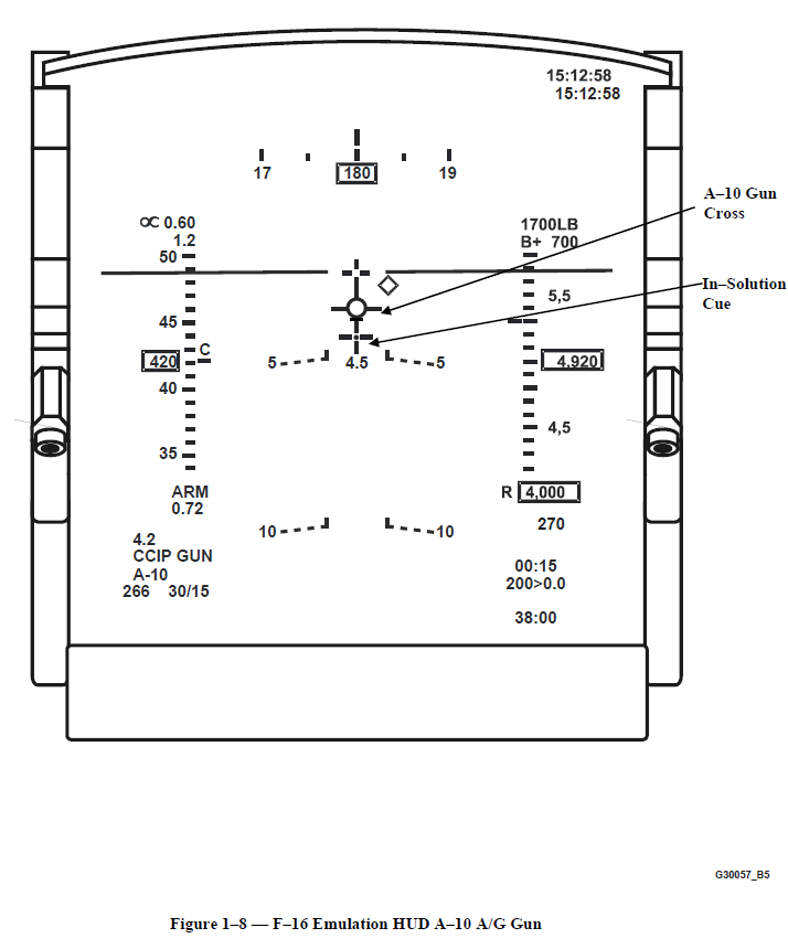
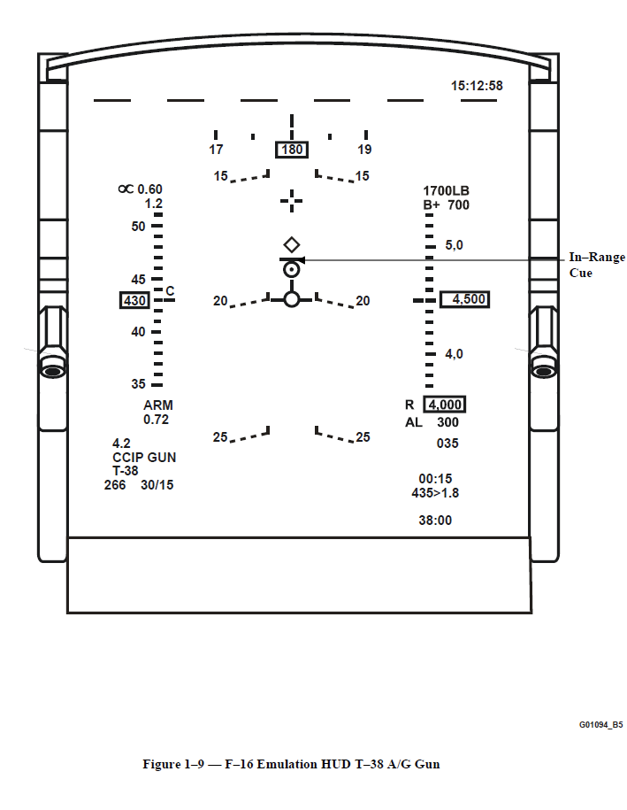
CCIP Gun
1. Gun firing or strafing is selected via the UFCP (CCIP at UL-2 and Gun in UR-1)) or (if either CCRP or CCIP is
selected on the UFCP and A/G Master Mode is selected on the stick) toggling to CCIP Gun with the weapons mode
switch on the throttle. Two separate gun employment options are available – the A–10 gunsight and the T–38 gunsight.
On the MFD WPN page when GUN is selected on MR-3, MR-4 toggles between A–10 and T–38 gunsight. When the
gun mode is selected the BFL and command steering line are removed from the HUD and selected gun is displayed on
HUD. Slightly different ballistics (drag, weight, projectile fly-out speed) are computed for the A-10 30 mm round.
2. The A–10 gunsight is the default gun mode.
a. A gun cross with a dot in the center is the aiming device for the simulated GAU–8 30 mm gun. When the slant
range to bullet impact is less than 4.9 nm, the slant range (in tenths of a nautical mile) is displayed under the cross
and a short horizontal line is shown on top of the cross. This is the “in–solution” or in–range cue. (See Figure 1–8).
b. When beyond 5 nautical miles or gun cross is at edge of the HUD an “X” is displayed on top of the cross.
3. The T–38 gunsight simulates the M61A1 20 mm (F–16) gun. The aiming device is a pipper (small circle with a dot
inside). This pipper is the same as the CCIP bomb pipper.
a. An “in–range” (4000 ft or less) cue is displayed above the pipper to give a relative distance to the target.
When the “in–range” cue moves down and attaches to the top of the pipper, the slant range is 4,000 ft or less. (See
Figure 1–9.)
b. The slant range to the target is displayed (to the nearest hundred feet) on the HUD just below the altitude alert
data block. The system uses a barometric algorithm to determine the range to the target based on the target's
elevation and your current flight parameters.
4. The gun is fired by pulling the trigger and will continue to fire as long as the trigger is pulled and rounds remain.
5. The break–X feature used in the bombing mode is available in the CCIP Gun mode (A–10 or T–38) as well.
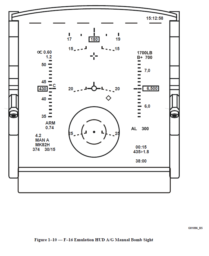
Manual Bombs and Gun
1. The MAN sub–mode is selected on the UFCP weapons display. MAN replaces CCIP or CCRP on the lower left
side of the HUD next to the selected weapons program (A, B, C, D, E, F, GUN).
2. The manual bomb reticle for the F–16 emulation HUD consists of a pipper and a double ring. The center 50 mil
diameter ring is dashed and the outside 100 mil diameter ring is solid, see Figure 1–10. The reticle is placed on the
HUD in a roll stabilized position equal to the mil depression required for the selected weapon.
3. The A–10 manual gun sight is the same cross, but no range (x.x nm) info is displayed below the cross. Similarly,
the T-38 manual gun sight is the same pipper; however there is no in–range cue (short horizontal line which attaches to
the pipper at 4000 ft). The pilot must estimate when the target is within effective range for the selected gun type.
4. The pilot must fly the aircraft into position and visually make any corrections necessary to get the bomb/bullets on
target. When the pickle button is depressed the bomb is released. When the trigger is pulled the gun is fired. A
Break-X is displayed as programmed in both manual bomb and gun modes. A delayed type release is not available for
this sub–mode.
11
5. A LOW cue is displayed in the Manual submode for the CBU–87 if weapon release will result in fuse activation
below the Height Of Function.
CCRP Bombs
1. The Continuously Computing Release Point (CCRP) mode provides an “indirect” (the pilot probably does not have
visual on the target at weapon release) weapons delivery capability. Indirect bombing includes loft or toss type
deliveries and level deliveries from medium/high altitude. The CCRP mode in the T–38C closely resembles the F–16
CCRP delivery mode.
2. Just like in the CCIP bomb mode, changes are made to the F–16 emulation HUD display to show specific CCRP
delivery symbols/information not included in the NAV master mode or the A/A master mode (see Figure 1–11). The
following information is added, replaced, or changed on the HUD when changing from NAV to the CCRP sub–mode:
a. The weapon delivery status is changed to ARM from SAFE when the master arm switch is moved to the
armed position.
b. The avionics master mode/sub–mode indicates CCRP and the weapon program (A, B, C, D, E, F and each
associated weapon type) that is elected.
c. Under the Max G and avionics master mode/sub–mode data block is a read out of the gun rounds remaining
and chaff/flares remaining.
d. The bank angle scale and bank indicator are removed.
e. For an optimum toss range delivery, a vertical Azimuth Steering Line (ASL) provides wind corrected
command cueing (heading) to the target. A Pull–Up Cue (staple) appears below the FPM on the ASL 10 seconds
before the estimated pull–up and it moves up towards the FPM on the ASL. Flying to this pull–up cue will achieve
an optimum range 30° climb release. A Solution Cue (horizontal line) is also shown above the FPM on the ASL
approximately 5 seconds before release and moves down the ASL toward the FPM.
f. A Maximum Toss Anticipation Cue circle appears 2 seconds prior to the estimated pull–up to achieve
maximum toss range (approximately 40° climb for release). Minimum afterburner may be required to maintain
airspeed and achieve maximum toss bomb range. Once the solution (bomb release) is achieved, the circle flashes
for 2 seconds and then is removed.
g. The slant range to the target is computed via algorithms and displayed below the altitude alert data block. The
slant range is displayed in tenths of nautical miles based on EGI data (E x.x). A time to pull–up (TPUL) or time to
release point (TREL) is displayed below the slant range. The next line displays bearing and ground track range in
nm to the target.
h. When CBU–87 is the bomb program on the A/G submode (CCRP A, B, C, D, E, or F), a LOW cue may be
displayed under the horizon line. This indicates that the projected apex of the CBU–87 is below its Height Of
Function – 1200 ft. AGL (normally a fuze activation setting for optimum bomblet pattern). CBU87 weapon
release is inhibited when the CBU87 LOW cue is present. This LOW cue is also added to the CCIP and Manual
submodes for the CBU–87.
3. In the CCRP sub–mode all of the flight conditions, range to a designated target, range to the pull–up point,
optimum weapon release and weapons ballistics parameters are combined to provide an azimuth steering line (ASL)
with a pull–up cue and a solution (weapon release) cue on the HUD. The aircraft is flown to get the flight path marker
(FPM) centered over the ASL. When the pull–up cue is reached a climb is initiated until bomb(s) release.
Alert Tones
1. The avionics system provides advisory tones as an additional cue to the pilot in a head–up environment. The three
tones that are important in the A/G arena are: G tone, trigger and pickle button tones, and CMD activation tone.
2. There are four separate G warning tones. From 85–92% of the computed G limit a 900Hz (w/ 4Hz modulation)
tone sounds. From 92–98%, a 900Hz (w/ 8Hz modulation) tone sounds. The tone changes to a steady 900Hz over 98%
of the G limit and converts to an alternating 250Hz / 900Hz tone above 100% of the computed G limit.
3. When the CMD switch is moved to either position a modulated tone is heard in the headsets to indicate the
program has started. The tone will only be heard as long as the switch is in an activation position.
4. When either the pickle button is pressed or the trigger is pulled a steady tone is heard for as long as the button is
pressed or the trigger is pulled.
5. If the VTR is operating when these tones occur they are recorded on the audio track of the tape. The tones can
provide another event cue (along with the CTVS mark) on the tape for use during mission debrief.

No Drop Bomb Scoring (NDBS)
Objective 6 — Interpret the data presented on the No Drop Bomb Scoring system and the Summarized Scoring
Display.
1. The No Drop Bomb Scoring system provides immediate feedback on the results of the bombing run. The NDBS
displays the release parameters along with the calculated hit point graphically and digitally on the MFD. The VTR will
automatically record the NDBS data from any VTR mode other then STOP. The summarized scoring display
information is also saved to the MDP for download via the DTS.
2. The NDBS overall accuracy is limited to the navigational accuracy of the aircraft and the quality of the target
coordinates and altitude definitions.
3. The scoring presentation provides a comparison of nominal (planned) release parameters with the following actual
aircraft parameters:
a. Altitude
b. Dive angle
c. Velocity
4. The NDBS display shows aircraft attitude (side slip and bank angle) and an analog display of target point, aim
point, and hit point.
5. When using the CCIP sub–mode with an immediate release, the NDBS displayed score will be the same as the
displayed aiming. Assuming you have the pipper on the target when you pickle, this will result in a direct hit. When
performing a delayed release, pilot error can be added. The results of these errors will be displayed on the NDBS with
the addition of relative score.
Scoring Display
1. There are two types of scoring displays:
a. Auto Scoring display of the current release data.
b. Summary table display of all the releases for this mission (up to 20 releases).
2. The scoring display is automatically presented 10 seconds after the release and replaces any other MFD display.
Auto Scoring Display — The auto scoring display will graphically show how well the bombing run was performed,
see Figure 1–12. The graphical aim or hit symbol is not shown if the aim point or hit point is greater than 320 ft from
the target. If the same point is also greater than 999 ft from the target the digital display will only be shown as three
X’s. The following information is presented on the automatic display:
1. Release number for the current flight.
2. Type of weapon that was used.
3. Reticle depression set for the MAN sub–mode.
4. Digital aim point in relation to the target in feet and clock position.
5. Digital score (SCORE) relative to the target coordinates in feet and clock position.
6. Relative score (REL SCOR) in feet and clock position to the target’s aiming point. REL SCOR only applies to a
delayed CCIP release or MAN release.
7. Type of release performed including delay time (above aircraft heading at release).
8. Aircraft heading at time of release (above reference circles/range rings).
9. Wind speed and direction at release altitude (the wind caret above and right of reference circles).
10. Graphical depiction of target with three 100 ft range rings/reference circles.
11. Graphical analog display of hit point (inverted triangle).
12. Graphical analog display of aim point (plus sign).
13. Additional actual flight parameters:
a. Side slip in degrees
b. Bank angle in degrees
c. Off–track flight path in feet (shown for a CCIP delayed release only)
14. Digital display of aircraft deviation from nominal (planned) release parameters (shown in next lower set of data on
MFD) (+ sign means greater than nominal; – sign means less than nominal).
15. Nominal release parameters that were initially set (planned airspeed, release altitude and dive angle).
16. Triangle diagram display of actual flight parameters at release point:
a. Altitude
b. Speed (KCAS)
c. Dive angle
d. Aircraft Gs at release
Summarized Scoring Display — The summarized scoring display presents the scoring information for all the
bombing runs made during that flight, see Figure 1–13. If the aim point or hit point is greater than 999 ft then the
digital display is only shown as three X’s. If there are more than four bombing runs then MB-6 (NEXT) will bring up
the next page. The following summary information is presented:
1. Release number
2. Type release, manual depression, and weapon type.
3. The aim point relative to target coordinates, score relative to the target, and score relative to aim point.
4. Actual flight parameters at release:
a. Side slip
b. Bank
c. Deviation from track (MAN or delayed)
5. Delayed release time.
6. Aircraft Gs at weapon release in tenths of a G.
7. Actual release parameters (speed, release altitude and dive angle).
Data Transfer System (DTS)
1. Streaming INS (ownship position) data and flight loads data are recorded to the MDP from first aircraft motion to
30 seconds after landing (WOW and less than 60 knots). Using the Data Analysis program a position/performance file
is extracted that can be used with the Mission Debrief Station (MDS) to present a graphical depiction of the flight. The
captured data includes: latitude, longitude, altitude, time, speed, heading, AOA and G’s, plus event notification
(weapon/CMD release, scoring, stall, etc.). Ninety minutes of recording time is available. Transfer of all remaining
maintenance and operational MDP data to the DTC is automatically accomplished at the end of the flight or after
termination of data recording. The DTC is taken to maintenance debrief for download to Integrated Maintenance
Information System (IMIS).
2. MDS information includes aircraft position and flight performance information, plus relative (pairing) information
between flight members and NDBS scores for the flight. As many as four aircraft can be displayed at the same time to
show how the weapon delivery patterns were flown for debrief. The mission debrief data and flight loads data are
written directly to the DTC during flight to allow more data to be recorded and to reduce the post–flight download
times on the ground.
Summary
The A/G master mode provides the pilot three basic submodes to employ bombs and to strafe. Four sights can be
selected – CCIP, CCIP GUN, CCRP or MAN. The HUD symbology is modified to give the pilot a CCIP, CCRP, or
MAN sight to aim the bombs at the target and to maintain track if the bomb release is delayed. The same CCIP or
MAN sights are used to aim the gun in a strafing pass. All of the parameters of the A/G engagement are recorded via
the VTR for later review and analysis. The NDBS system scoring information is also written to the MDP for later
download via the DTS.
SA–1 — Review Exercise
Complete the following review exercise for the A/G master mode. Answers are in the back of the SG.
1. What, UFCP selectable, sub–modes are available in the A/G master mode?
a. only Bomb program A, B, C, D, E, F, and Gun
b. CCIP, CCRP and Manual
c. CCIP, CCRP and LCOS
d. SRM and DGFT
2. In the A/G master mode the velocity scale on the HUD, can be changed on the UFCP weapons menu to display
either TAS or CAS.
a. True
b. False
3. The mission planning center (MPC/JMPS) can be used to pre–define the weapons load programs: A, B, C, D, E, F
and Gun.
a. True
b. False
4. The Master Arm Switch must be in the ARM position to enable the Counter Measures Dispensing Switch.
a. True
b. False
5. If CCIP or CCRP is selected on the UFCP, what A/G function(s) are selectable by the weapon mode switch on the
right throttle?
a. Selection of the A/G Master Mode
b. Simulated gun firing
c. Toggling between CCIP bombs, CCIP guns and CCRP
d. Ground target designation
6. An event (CTVS/video) mark is placed on the VTR tape every time the ______________ .
a. trigger is pulled
b. pickle button is released
c. pickle button is depressed
d. a and c above
7. The bomb release will be delayed when the mil depression of the pipper is _________ ?
a. 2,000 to 3,000 meters
b. <170 mils
c. >200 yds
d. >170 mils
22
8. The HUD items that are removed from the A/G mode display using the declutter function are selected prior to
flight on the MPC/JMPS and cannot be changed in flight.
a. True
b. False
9. During the pull–up from the bombing dive pattern you should hear the 250/900Hz modulated (at 2 Hz) G tone to
indicate you are pulling sufficient G.
a. True
b. False
No comments to display
No comments to display